

Blog
Jointer, Planer, or Combination Machine? Mapping the Stock-Preparation Workflow

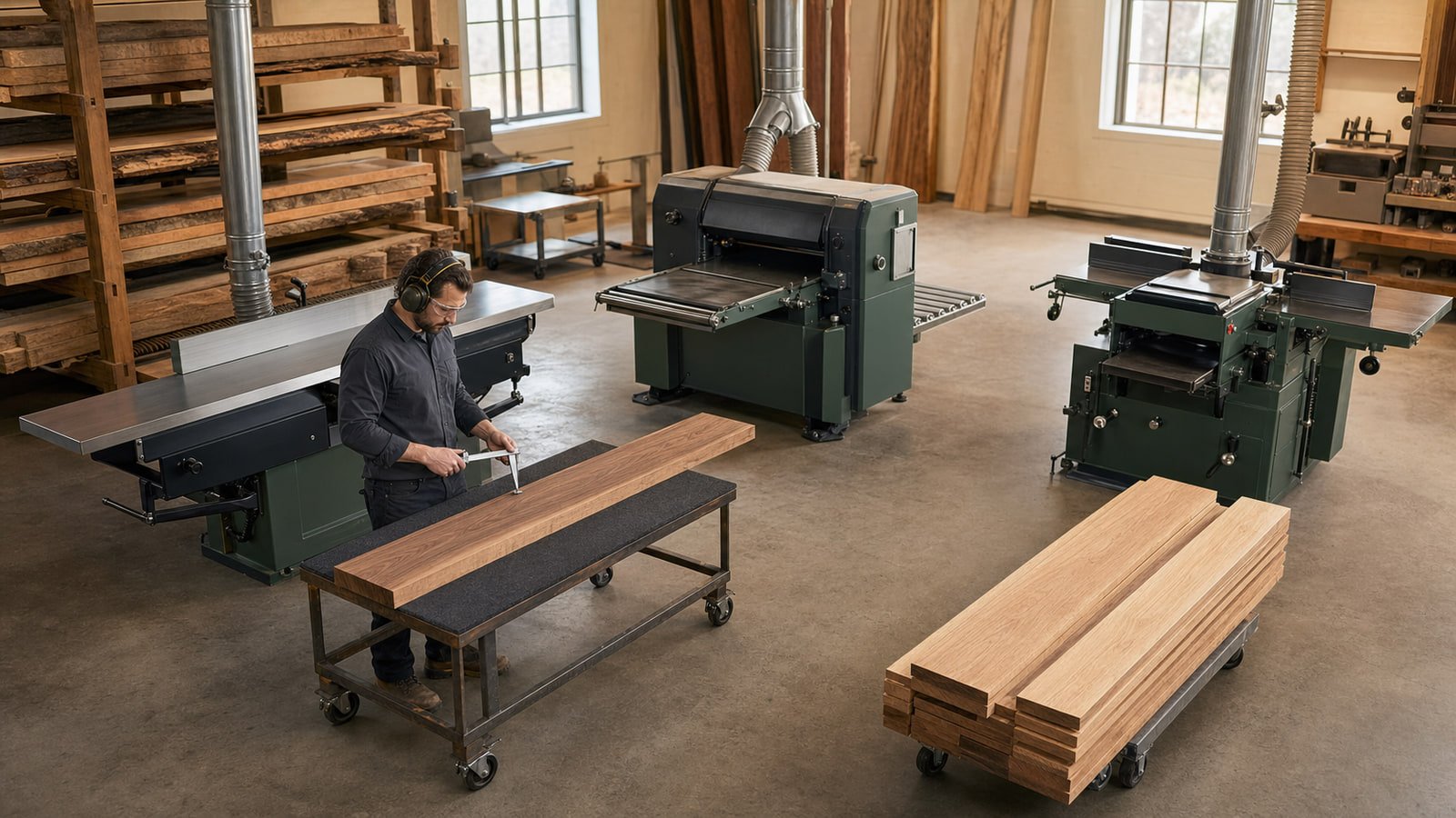
Planing & Jointing
Jointer, Planer, or Combination Machine? Mapping the Stock-Preparation Workflow
Understand what each machine contributes to flattening, straightening, and thicknessing stock before deciding between separate and combination equipment.
Rough stock rarely enters a shop flat, straight, square, and uniform in thickness. Jointing and planing address different reference surfaces, which is why the correct equipment decision starts with the complete preparation sequence—not with two machines that happen to share a working width.
A jointer, thickness planer, and jointer-planer combination can all belong in a professional workflow. The best fit depends on stock dimensions, required output, available floor space, operator movement, and how often the process changes from one operation to the other.
Understand the role of each operation
Jointing establishes a reference
A jointer is generally used to create a flat face or a straight edge that can serve as a reference for later machining. The workpiece passes over a rotating cutterhead between infeed and outfeed tables.
The machine does not automatically make the opposite face parallel or bring the board to a final, uniform thickness. Its primary contribution is a controlled reference surface or edge.
Planing creates a parallel surface
A thickness planer references one face of the workpiece against its table while cutting the opposite face. When the reference face is properly prepared and the stock is supported, the operation can bring parts toward a consistent thickness.
A planer is not a substitute for establishing a suitable reference face. Feeding twisted, bowed, or otherwise unstable stock into a planer can reproduce or shift the problem rather than correct it.
Combination machines share a platform
A jointer-planer combination provides both operations in one machine platform. This can reduce total machine footprint and consolidate dust and utility connections, depending on the design. It also introduces a changeover between jointing and planing modes.
That tradeoff is neither automatically positive nor negative. It must be evaluated against the shop’s actual sequence, batch sizes, staffing, and floor-space limits.
Map the current stock-preparation sequence
Follow several representative boards through the shop and record:
- How incoming stock is inspected and staged
- How defects, grain direction, and usable dimensions are identified
- Which face or edge is established first
- How many jointing and planing passes are typical
- Where length and width are established
- How parts are checked for flatness, squareness, and thickness
- Where prepared components wait for the next operation
Note any repeated walking, lifting, restacking, or searching for settings. A floor-space-saving machine may improve one constraint while creating extra handling if every part must be moved or restacked during changeover.
Compare separate machines with a combination
Separate jointer and planer machines can allow both stations to remain set for their respective operations. They may suit shops that process larger batches, move stock through a fixed sequence, or need two operators to work at the same time. The tradeoffs can include greater floor space, separate dust drops, additional electrical connections, and more equipment to maintain.
A combination machine can suit a shop where footprint matters and the work can be organized into sensible batches. Evaluate:
- Steps required to change modes
- Time and physical effort involved
- Whether fences, guards, tables, hoods, or dust connections move
- Whether settings are retained after changeover
- How parts are staged between the two operations
- Whether jointing and planing can ever be required simultaneously
Perform the complete changeover during a demonstration if possible. A brochure description cannot show whether the sequence suits the operator and production rhythm.
Define the stock range
Record routine and maximum board width, length, thickness, and weight. Also identify the shortest and thinnest parts the shop intends to process. Confirm every minimum and maximum against current documentation for the exact model.
Long stock needs stable infeed and outfeed handling. The operating footprint must include the full board length, operator position, supports, and safe movement around nearby equipment. Heavy or wide material may require mechanical assistance or a different staging plan.
Do not select working width from lumber purchase dimensions alone. Account for the usable width needed after inspection and initial breakdown, as well as the parts the shop intends to keep in one piece.
Review tables, fence, feed, and adjustment
For jointing, compare table length, table construction, adjustment method, fence size and movement, guard arrangement, depth-of-cut control, and access for calibration. Longer parts depend on stable support and a properly set relationship between the infeed table, cutterhead, and outfeed table.
For planing, review table support, feed system, thickness adjustment, readout, head locking where applicable, and the procedure for managing infeed and outfeed effects. Ask how bed rollers, pressure components, and feed rollers are adjusted and maintained.
On a combination machine, verify how the shared components behave in both modes and how dust extraction is redirected.
Choose the cutterhead and knives as a system
Cutterhead designs and knife systems differ in cutting action, setup, service, and consumable cost. Compare the exact head installed on the quoted machine and confirm:
- Knife or insert type and dimensions
- Approved maximum speed and operating limits
- Replacement and rotation procedure
- Setup tools or gauges required
- Availability of consumables
- Sharpening pathway, when applicable
- Torque and inspection requirements
- Suitability for the materials being processed
Surface quality is influenced by grain, moisture, stock condition, feed, depth of cut, cutter condition, machine setup, and material support. Use representative test material instead of relying on a universal finish claim.
Plan dust collection and chip handling
Jointing and planing can generate a substantial volume of chips. Confirm port locations and the extraction requirements for each operating mode. For a combination machine, determine whether the hood or connection must be repositioned and how the operator verifies correct setup before starting.
The dust-control system must be evaluated for the required airflow and resistance of the actual duct path. Also consider container capacity and the practical volume of waste produced during long preparation runs.
Verify power, space, and receiving needs
Check supply voltage, phase, frequency, full-load information, disconnect, and other electrical requirements for the exact machine. Have a qualified electrician assess the proposed connection. Draw the service-clearance and board-handling envelope on the floor plan, not just the machine footprint.
Before delivery, confirm packaged dimensions and weight, unloading method, door and aisle clearances, floor conditions, final placement, and any assembly or commissioning scope in the accepted written order or quotation.
Information to include in a stock-preparation request
Prepare:
- Wood species and typical incoming condition
- Routine and maximum board dimensions
- Desired finished dimensions and surface standard
- Batch sizes and processing frequency
- Current preparation sequence
- Available floor and material-staging space
- Whether simultaneous jointing and planing is needed
- Electrical and dust-collection information
- Preferred cutterhead or current knife system, if any
- Receiving and access constraints
The equipment choice becomes clearer when the shop can see where the reference surface is created, how thickness is established, and how material moves between those steps.
Compare Planing and Jointing Equipment
Share the machine, material, application, utilities, and site details that matter to your project.
Compare Planing and Jointing EquipmentRelated Reading
More Machinery Guidance
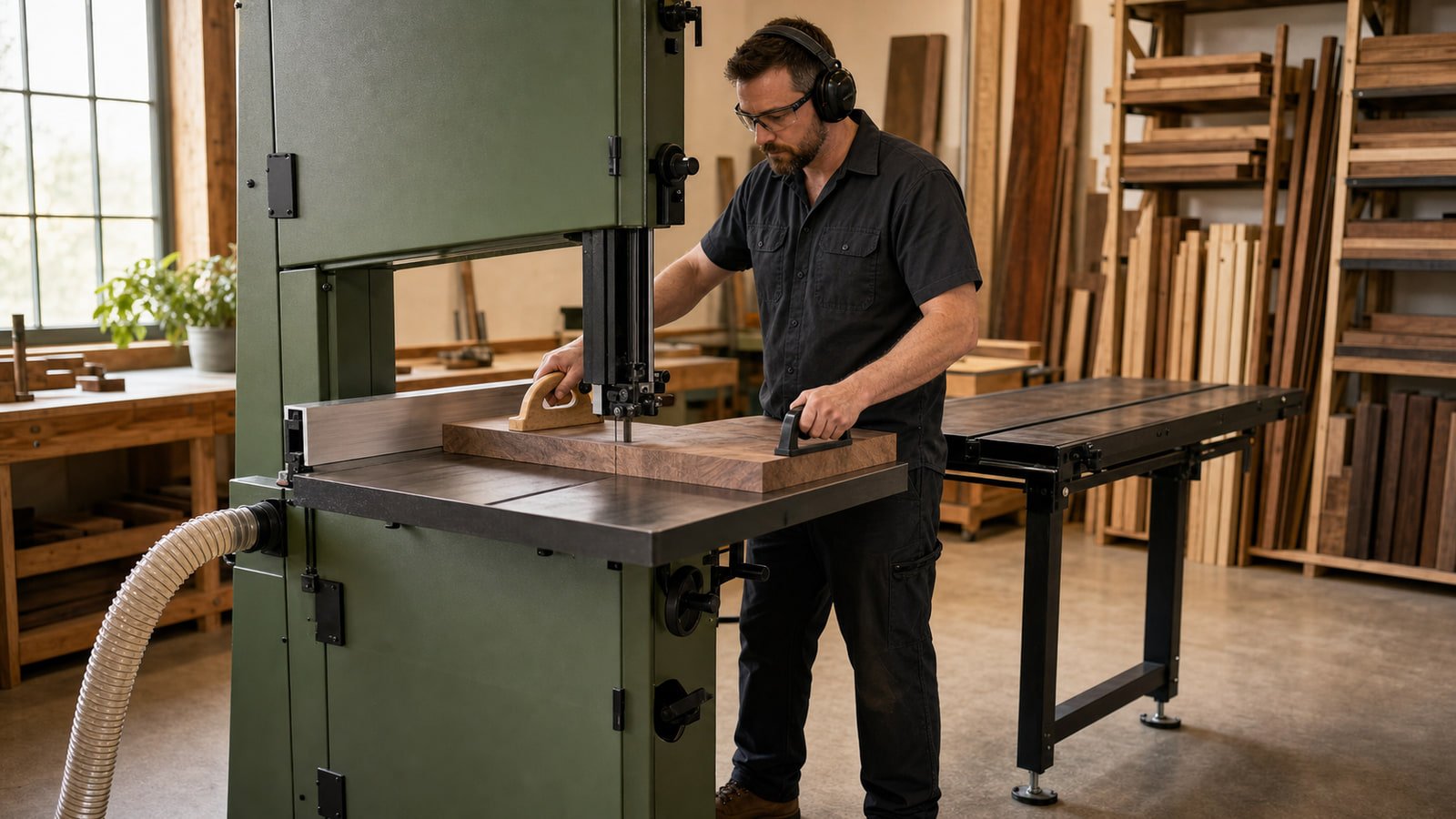
How to Choose a Bandsaw and Blade for the Work You Actually Cut
Match the bandsaw format, cutting envelope, blade, feed method, support, power, and dust collection to the material and cuts your shop performs.
Read guide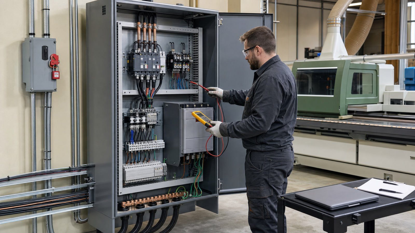
Single-Phase vs. Three-Phase Woodworking Machinery: What to Verify Before Ordering
Confirm the machine nameplate, facility supply, complete connected load, and qualified electrical plan before placing a machinery order.
Read guide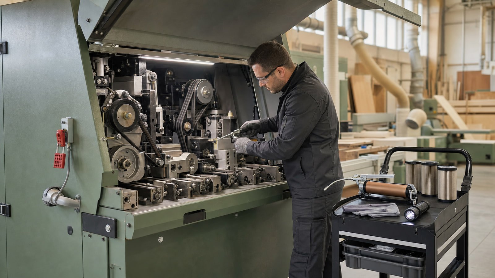
A Practical Preventive-Maintenance Plan for Industrial Woodworking Machinery
Build a manufacturer-led maintenance system around machine condition, operating hours, dust and residue, tooling, utilities, safety devices, records, and assigned responsibility.
Read guide